
The Engineer's Ultimate Guide to Bearing Types: Selection, Load Analysis, and Failure Prevention
 Mia
Mia
I. Introduction: The Unsung Heroes of Motion
In the world of rotating machinery, from the smallest electric motor to the largest wind turbine, the bearing is the silent, indispensable component that enables smooth, low-friction motion. Bearings support moving parts, reduce friction, and transfer loads, making them the foundation of modern engineering. However, the sheer variety of bearing types—each optimized for specific loads, speeds, and environments—makes selection a critical and often complex task.
This guide provides a deep analysis of bearing types, going beyond simple classification to focus on the engineering principles of load analysis, selection criteria, and failure prevention. Our goal is to equip engineers and designers with the knowledge to select the right bearing for maximum performance and longevity.
II. The Fundamental Classification: Rolling Element vs. Sliding Contact
Bearings are fundamentally classified by their operating principle: whether they use rolling elements to separate surfaces or rely on a film of lubricant for sliding contact.
Rolling Element Bearings
Rolling element bearings, such as ball and roller bearings, use spherical balls or cylindrical rollers to maintain separation between the moving and stationary parts (races). This mechanism converts sliding friction into much lower rolling friction, making them suitable for high-speed and high-precision applications.
Sliding Contact (Plain) Bearings
Sliding contact bearings, often called plain bearings, bushings, or journal bearings, operate without rolling elements. They rely on a layer of lubricant (oil, grease, or even air) or a self-lubricating material to create a low-friction interface. They are typically simpler, more compact, and excellent for high-load, low-speed, or oscillating applications where shock resistance is critical.
The Hydrodynamic Bearing Principle
A specialized and highly effective form of plain bearing is the hydrodynamic bearing, which operates based on the **Hydrodynamic Bearing Principle**. This principle relies on the relative motion between the shaft (journal) and the bearing surface to generate a pressurized wedge of lubricant. This wedge completely separates the two surfaces, resulting in near-zero friction and wear during operation. Hydrodynamic bearings are indispensable in heavy-duty, high-speed applications like large turbines and compressors where load capacity is paramount. The design requires precise tolerances and a continuous supply of lubricant to maintain the fluid film, making them a complex but highly reliable solution for critical machinery.
Non-Contact Bearings
For specialized, extremely high-speed, or ultra-low-friction applications, non-contact bearings like magnetic bearings (using magnetic fields) or fluid bearings (using pressurized gas or liquid) are employed. These are highly complex and reserved for niche fields like turbomachinery and high-precision manufacturing.
III. Core Engineering Principle: Load Analysis (Radial vs. Thrust)
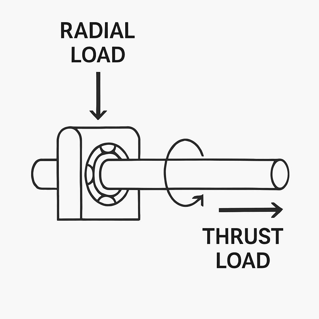
The most critical factor in bearing selection is the type of load the bearing must support. Loads are primarily categorized as radial, thrust (axial), or a combination of both.
| Load Type | Definition | Direction | Typical Application |
|---|---|---|---|
| Radial Load | Force acting perpendicular to the axis of rotation. | Perpendicular to shaft | Gears, pulleys, electric motor rotors. |
| Thrust (Axial) Load | Force acting parallel to the axis of rotation. | Parallel to shaft | Propeller shafts, vertical shafts, worm gears. |
| Combined Load | A combination of both radial and thrust forces. | Diagonal to shaft | Tapered roller bearings in car wheel hubs. |
Bearings are specifically designed to handle one or both of these load types efficiently. Selecting a bearing designed primarily for radial loads to handle a heavy thrust load will lead to premature failure.
IV. Deep Dive into Rolling Element Bearing Types
Rolling element bearings are the most common in industrial applications. Their design variations are optimized to handle specific load combinations and operating conditions.
1. Ball Bearings
Ball bearings use spherical rolling elements, which contact the races at a small point. This allows for high-speed operation and low friction, but limits their load capacity compared to roller bearings.
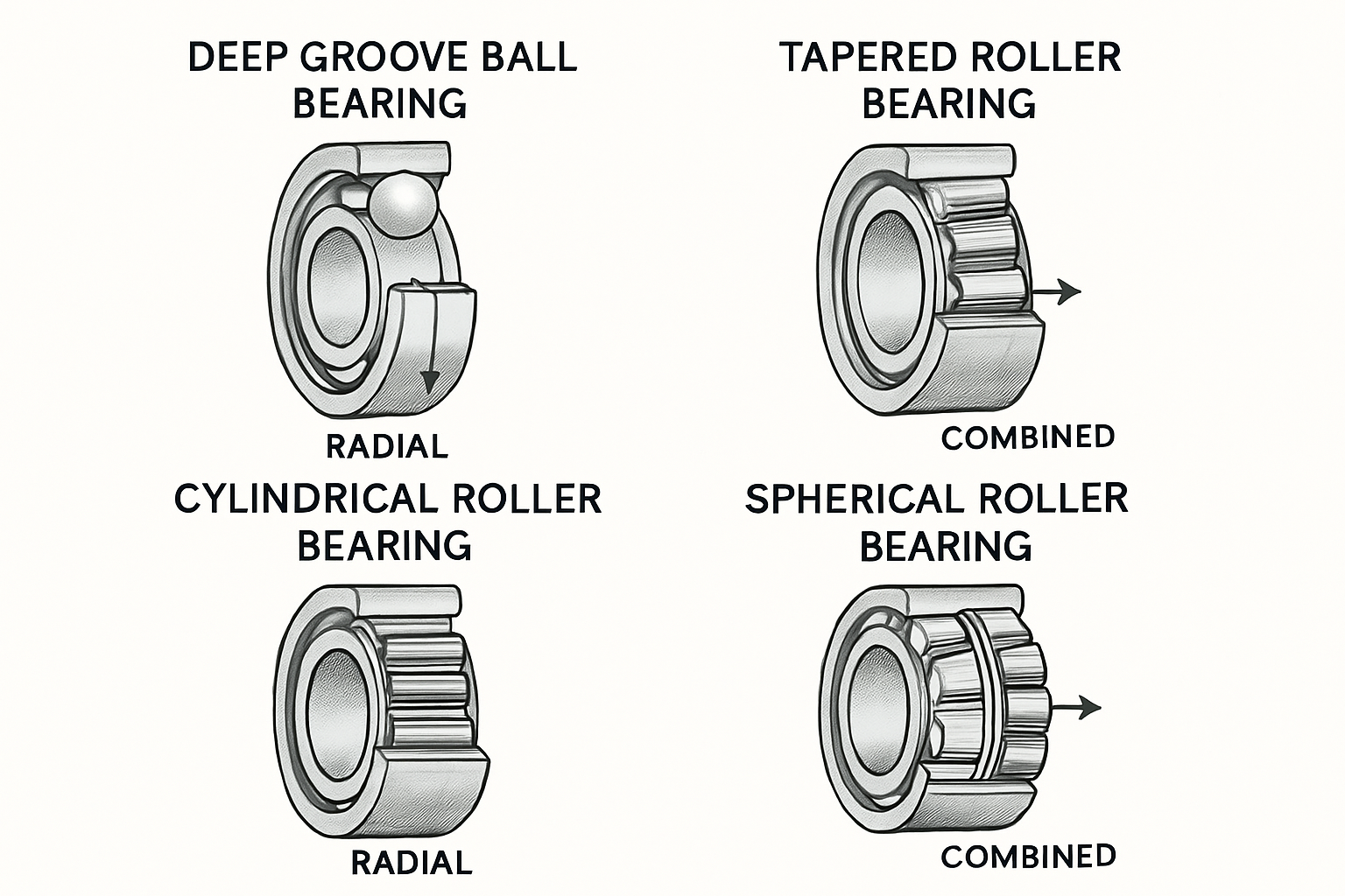
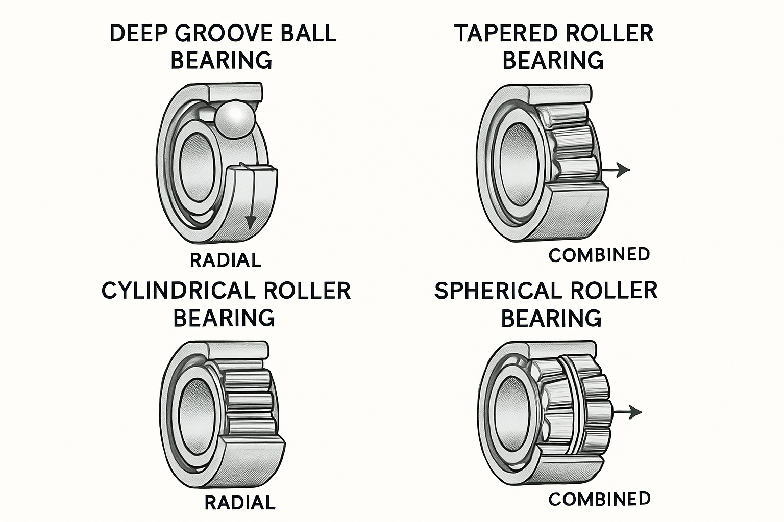
- Deep Groove Ball Bearings (DGBB): The most widely used type. They handle moderate radial loads and moderate thrust loads in both directions. They are known for high speed capability and low maintenance.
- Angular Contact Ball Bearings (ACBB): Designed with raceways offset from each other, allowing them to support high combined (radial and thrust) loads. They are often mounted in pairs (duplex) to support thrust loads in both directions and increase stiffness.
- Self-Aligning Ball Bearings (SABB): Feature two rows of balls and a common spherical outer ring raceway. This design allows the bearing to accommodate angular misalignment between the shaft and housing, making them ideal for long shafts or applications where mounting precision is difficult.
2. Roller Bearings
Roller bearings use cylindrical, tapered, or spherical rollers, which contact the races along a line rather than a point. This line contact significantly increases the contact area, allowing them to support much higher loads than ball bearings.
- Cylindrical Roller Bearings (CRB): Excellent for very high radial loads and high speeds. Due to the parallel alignment of the rollers, they typically handle little to no thrust load, though some designs (like NU or NJ types) can handle light thrust loads.
- Tapered Roller Bearings (TRB): Use truncated cone-shaped rollers and raceways. This geometry makes them uniquely suited to handle very high combined radial and thrust loads simultaneously. They are commonly used in vehicle wheel hubs, gearboxes, and industrial machinery.
- Spherical Roller Bearings (SRB): Feature two rows of barrel-shaped rollers and a spherical outer ring raceway. Like SABBs, they can accommodate significant angular misalignment, but their line contact allows them to support extremely high radial and heavy thrust loads.
- Needle Roller Bearings (NRB): Use very long, thin cylindrical rollers. They offer an extremely high radial load capacity relative to their cross-section, making them ideal for applications where radial space is severely limited (e.g., automotive rocker arm pivots, transmissions).
V. The Critical Selection Guide: Beyond the Basics
Selecting the correct bearing involves a systematic process that goes beyond simply matching the load type.
Step 1: Load and Speed Analysis
The first step is to quantify the load (static and dynamic) and the required operating speed (RPM).
- Load: The bearing's basic dynamic load rating ($C$) and static load rating ($C_0$) must be compared against the application's equivalent dynamic load ($P$) and static load ($P_0$).
- Speed: High speeds generate heat. Ball bearings are generally preferred for higher speeds due to lower friction, while roller bearings are limited by the heat generated from their larger contact area.
Step 2: Life and Reliability Calculation
Bearing life is typically calculated using the $L_{10}$ life formula, which represents the number of revolutions (or hours) that 90% of a large group of identical bearings will meet or exceed before the first sign of fatigue failure (spalling).
$$L_{10} = (\frac{C}{P})^p$$
Where $p$ is the life exponent (3 for ball bearings, 10/3 for roller bearings). Engineers must factor in reliability adjustments, contamination factors, and lubrication quality to determine the required bearing life.
Step 3: Bearing Preload Calculation
For high-precision and high-stiffness applications, such as machine tool spindles and aerospace systems, eliminating internal clearance is paramount. This is achieved through **Bearing Preload Calculation**, which involves applying a controlled internal axial load to the bearing. Proper preload is critical to optimize system stiffness, reduce running noise, and prevent the rolling elements from skidding under light load conditions. However, excessive preload can drastically reduce bearing life by increasing internal stresses and operating temperature. Therefore, precise calculation—often using spring loading or controlled axial displacement—is necessary to find the optimal balance between stiffness and longevity.
Step 4: Environmental and Operational Factors
Bearing life is typically calculated using the $L_{10}$ life formula, which represents the number of revolutions (or hours) that 90% of a large group of identical bearings will meet or exceed before the first sign of fatigue failure (spalling).
$$L_{10} = (\frac{C}{P})^p$$
Where $p$ is the life exponent (3 for ball bearings, 10/3 for roller bearings). Engineers must factor in reliability adjustments, contamination factors, and lubrication quality to determine the required bearing life.
Step 3: Environmental and Operational Factors
- Misalignment: If the shaft and housing cannot be perfectly aligned, use Self-Aligning Ball Bearings or Spherical Roller Bearings.
- Contamination: Applications with high dust or moisture require bearings with robust **sealing** (e.g., sealed or shielded bearings).
- Temperature: Extreme temperatures require specialized materials and lubricants (e.g., high-temperature grease or ceramic bearings).
| Bearing Type | Primary Load | Speed Capability | Misalignment Tolerance | Typical Application |
|---|---|---|---|---|
| Deep Groove Ball | Moderate Radial, Light Thrust | High | Low | Electric Motors, Gearboxes, Fans |
| Tapered Roller | High Combined (Radial & Thrust) | Moderate | Low | Car Wheel Hubs, Heavy Machinery |
| Cylindrical Roller | Very High Radial | High | Low | Rolling Mills, High-Load Gearboxes |
| Spherical Roller | Very High Radial, Heavy Thrust | Moderate | High | Vibrating Screens, Paper Mills |
| Needle Roller | Extremely High Radial (Small Space) | Moderate | Low | Automotive Transmissions, Rocker Arms |
VI. Bearing Failure Analysis: Prevention is Key
Bearing failure is the leading cause of downtime in rotating machinery. Understanding the common failure modes is crucial for maintenance and design improvement.
Common Failure Modes
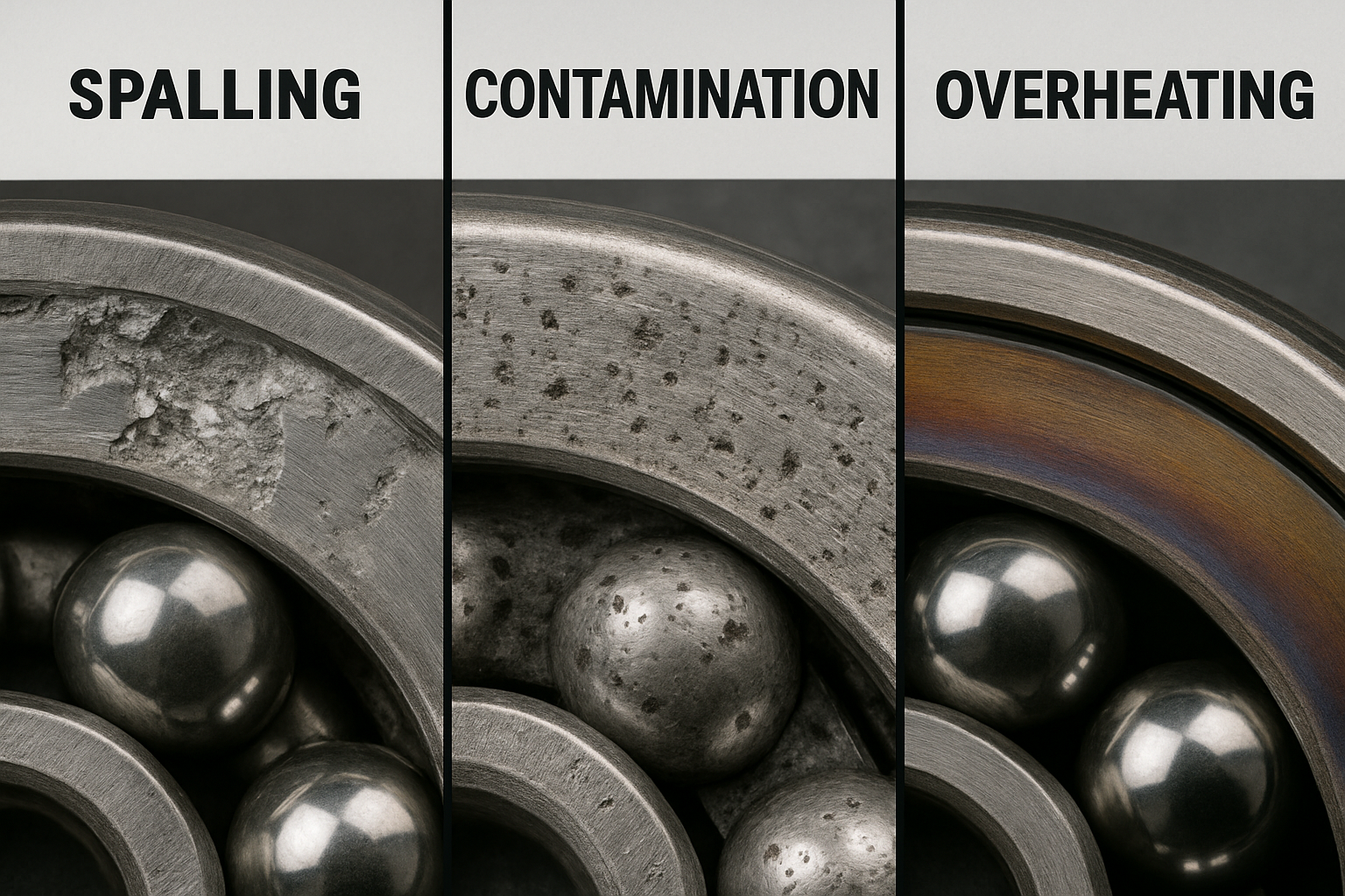
The three most common causes of premature bearing failure are:
- **Fatigue (Spalling):** The primary failure mode, characterized by flaking of the raceway or rolling element surface due to repeated stress cycles. This is a natural end-of-life failure, but can be accelerated by excessive load or poor installation.
- **Contamination:** The second leading cause. Hard particles (dirt, metal chips) or corrosive fluids (water, acid) enter the bearing, causing abrasive wear, indentation, and premature fatigue.
- **Lubrication Failure:** This includes insufficient lubrication (starvation), excessive lubrication (churning and overheating), or using the wrong type of lubricant. It leads to overheating, discoloration, and rapid wear.
- **Misalignment:** Causes uneven load distribution across the rolling elements, leading to localized overheating and premature fatigue on one side of the raceway.
Prevention Strategies
- **Sealing:** Always select the appropriate seal type (contact or non-contact) to prevent contamination.
- **Installation:** Use proper tools (e.g., induction heaters, hydraulic presses) to ensure correct mounting and prevent damage from hammering.
- **Lubrication:** Adhere strictly to the manufacturer's lubrication schedule and use the specified grease or oil type.
Understanding Lubrication Regimes
Effective lubrication is governed by the **Bearing Lubrication Regimes**, which describe the state of the lubricant film relative to the surface roughness. These regimes range from **Boundary Lubrication** (surfaces are mostly in contact, high friction), through **Mixed Lubrication** (partial contact), to **Hydrodynamic (Full-Film) Lubrication** (surfaces completely separated by the fluid film, lowest friction). Reliability engineers must select the correct lubricant viscosity and operating speed to ensure the bearing operates primarily in the full-film regime, maximizing life and efficiency. Failure to maintain the correct regime, often due to contamination or insufficient viscosity, is the primary driver of premature wear and fatigue.
VII. Conclusion and Outlook
Bearings are far more than simple mechanical components; they are precision-engineered systems. Mastering the selection process—from accurately analyzing the load and speed requirements to understanding the nuances of different bearing types and anticipating failure modes—is fundamental to reliable machine design.
The future of bearings lies in **Smart Bearings**, which integrate sensors to monitor temperature, vibration, and lubrication in real-time. This predictive maintenance capability will revolutionize reliability engineering, moving the industry from reactive repair to proactive prevention.
VIII. Frequently Asked Questions (FAQ)
| Question | Answer |
|---|---|
| What is the main difference between a Ball Bearing and a Roller Bearing? | Ball Bearings use point contact, allowing for higher speed and lower friction. Roller Bearings use line contact, allowing them to support significantly higher loads. |
| What is the difference between Radial Load and Thrust Load? | Radial Load is a force perpendicular to the shaft (like a pulley load). Thrust Load (Axial Load) is a force parallel to the shaft (like a propeller load). |
| Which bearing type is best for handling misalignment? | Self-Aligning Ball Bearings (SABB) and Spherical Roller Bearings (SRB) are specifically designed to accommodate angular misalignment between the shaft and housing. |
| What does the L10 life formula represent in bearing selection? | L10 life is the number of revolutions (or hours) that 90% of a group of identical bearings will meet or exceed before the first sign of fatigue failure. It is the standard measure of bearing reliability. |
| What are the three most common causes of premature bearing failure? | The three leading causes are Fatigue (Spalling), Contamination (dirt/debris), and Lubrication Failure (insufficient or incorrect lubricant). |
| How does the life exponent ($p$) differ between ball and roller bearings in the $L_{10}$ formula? | The life exponent ($p$) is 3 for ball bearings and 10/3 (or $\approx 3.33$) for roller bearings. This difference reflects the contact geometry: point contact for balls and line contact for rollers. |
| Why are Angular Contact Ball Bearings (ACBB) typically mounted in pairs (duplex)? | ACBBs are mounted in pairs (e.g., back-to-back or face-to-face) to support thrust loads in both axial directions and to increase the overall stiffness of the bearing arrangement. |
| In what specific scenario is a Needle Roller Bearing (NRB) the ideal choice over a Cylindrical Roller Bearing (CRB)? | NRBs are ideal when radial space is severely limited (e.g., automotive transmissions or rocker arms), as they offer an extremely high radial load capacity relative to their very small cross-section. |
| What is the primary risk of over-lubrication in a high-speed ball bearing application? | Over-lubrication causes the rolling elements to churn the excess grease or oil, leading to a rapid increase in operating temperature and excessive friction, which can quickly degrade the lubricant and cause premature failure. |
| What is the key advantage of a Tapered Roller Bearing (TRB) over a Deep Groove Ball Bearing (DGBB) in a wheel hub application? | TRBs are uniquely designed to handle very high combined radial and thrust loads simultaneously, which is essential for vehicle wheel hubs that experience forces from both the vehicle weight (radial) and cornering/braking (thrust). |
References
- BDS Bearing. Bearing Types: The Technology to Make Life Easier.
- Fractory. Types of Bearings | Uses & Working Mechanisms Explained.
- SKF. Bearing selection process.
- GMN Bearing. Bearing Selection Guide | How to Choose a Bearing.
- Emerson Bearing. The Best Type of Bearing for Your Application: A Selection Guide.